Function Code
Read Coil Status (01)
Description :
Reads the ON/OFF status of discrete outputs (0X references, coils) in the slave.
Query:
The query message specifies the starting coil and quantity of coils to be read.
Coils are addressed starting at zero: coils 1–16 are addressed as 0–15.
Here is an example of a request to read coils 20–56 from slave device 17:
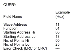
Read Coil Status – Query
Response:
The coil status in the response message is packed as one coil per bit of the data
field. Status is indicated as: 1 = ON; 0 = OFF. The LSB of the first data byte
contains the coil addressed in the query. The other coils follow toward the high
order end of this byte, and from ‘low order to high order’ in subsequent bytes.
If the returned coil quantity is not a multiple of eight, the remaining bits in the final
data byte will be padded with zeros (toward the high order end of the byte). The
Byte Count field specifies the quantity of complete bytes of data.
Here is an example of a response to the query
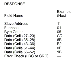
Read Coil Status – Response
The status of coils 27–20 is shown as the byte value CD hex, or binary 1100 1101.
Coil 27 is the MSB of this byte, and coil 20 is the LSB. Left to right, the status of
coils 27 through 20 is: ON–ON–OFF–OFF–ON–ON–OFF–ON.
By convention, bits within a byte are shown with the MSB to the left, and the LSB
to the right. Thus the coils in the first byte are ‘27 through 20’, from left to right.
The next byte has coils ‘35 through 28’, left to right. As the bits are transmitted
serially, they flow from LSB to MSB: 20 . . . 27, 28 . . . 35, and so on.
In the last data byte, the status of coils 56–52 is shown as the byte value 1B hex,
or binary 0001 1011. Coil 56 is in the fourth bit position from the left, and coil 52 is
the LSB of this byte. The status of coils 56 through 52 is: ON–ON–OFF–ON–ON.
Note how the three remaining bits (toward the high order end) are zero–filled.
Read Input Status (02)
Description :
Reads the ON/OFF status of discrete inputs (1X references) in the slave.
Query:
The query message specifies the starting input and quantity of inputs to be read.
Inputs are addressed starting at zero: inputs 1–16 are addressed as 0–15.
Here is an example of a request to read inputs 10197–10218 from slave device
17:
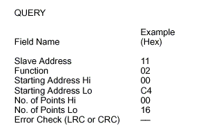
Read Input Status – Query
Response:
The input status in the response message is packed as one input per bit of the
data field. Status is indicated as: 1 = ON; 0 = OFF. The LSB of the first data
byte contains the input addressed in the query. The other inputs follow toward the
high order end of this byte, and from ‘low order to high order’ in subsequent bytes.
If the returned input quantity is not a multiple of eight, the remaining bits in the final
data byte will be padded with zeros (toward the high order end of the byte). The
Byte Count field specifies the quantity of complete bytes of data.
Here is an example of a response to the query
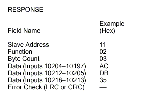
Read Input Status – Response
The status of inputs 10204–10197 is shown as the byte value AC hex, or binary
1010 1100. Input 10204 is the MSB of this byte, and input 10197 is the LSB.
Left to right, the status of inputs 10204 through 10197 is: ON–OFF–ON–OFF–
ON–ON–OFF–OFF.
The status of inputs 10218–10213 is shown as the byte value 35 hex, or binary
0011 0101. Input 10218 is in the third bit position from the left, and input 10213 is
the LSB. The status of inputs 10218 through 10213 is: ON–ON–OFF–ON–OFF–
ON. Note how the two remaining bits (toward the high order end) are zero–filled.
Read Holding Registers (03)
Description :
Reads the binary contents of holding registers (4X references) in the slave.
Query:
The query message specifies the starting register and quantity of registers to be
read. Registers are addressed starting at zero: registers 1–16 are addressed as
0–15.
Here is an example of a request to read registers 40108–40110 from slave device
17:
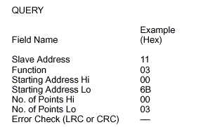
Read Holding Registers – Query
Response:
The register data in the response message are packed as two bytes per register,
with the binary contents right justified within each byte. For each register, the first
byte contains the high order bits and the second contains the low order bits.
Data is scanned in the slave at the rate of 125 registers per scan of the
controllers. The response is returned when the data is completely assembled.
Here is an example of a response to the query

Read Input Status – Response
The contents of register 40108 are shown as the two byte values of 02 2B hex, or
555 decimal. The contents of registers 40109–40110 are 00 00 and 00 64 hex, or
0 and 100 decimal.
Read Input Registers (04)
Description :
Reads the binary contents of input registers (3X references) in the slave.
Query:
The query message specifies the starting register and quantity of registers to be
read. Registers are addressed starting at zero: registers 1–16 are addressed as
0–15.
Here is an example of a request to read register 30009 from slave device 17:
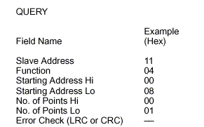
Read Input Registers – Query
Response:
The register data in the response message are packed as two bytes per register,
with the binary contents right justified within each byte. For each register, the first
byte contains the high order bits and the second contains the low order bits.
Data is scanned in the slave at the rate of 125 registers per scan of the
controllers. The response is returned when the data is completely assembled.
Here is an example of a response to the query
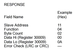
Read Input Registers – Response
The contents of register 30009 are shown as the two byte values of 00 0A hex, or
10 decimal.
Force Single Coils (05)
Description :
Forces a single coil (0X reference) to either ON or OFF. When broadcast, the
function forces the same coil reference in all attached slaves.
Query:
The query message specifies the coil reference to be forced. Coils are addressed
starting at zero: coil 1 is addressed as 0.
The reguested ON/OFF state is specified by a constant in the query data field.
A value of FF 00 hex requests the coil to be ON. A value of 00 00 requests it to be
OFF. All other values are illegal and will not affect the coil.
Here is an example of a request to force coil 173 ON in slave device 17:
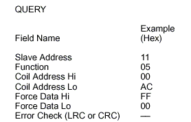
Force Single Coil – Query
Response:
The normal response is an echo of the query, returned after the coil state has
been forced.
Here is an example of a response to the query

Force Single Coil – Response
Preset Single Register (06)
Description :
Presets a value into a single holding register (4X reference). When broadcast, the
function presets the same register reference in all attached slaves.
Query:
The query message specifies the register reference to be preset. Registers are
addressed starting at zero: register 1 is addressed as 0.
The reguested preset value is specified in the query data field.
Here is an example of a request to preset register 40002 to 00 03 hex in slave
device 17:
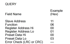
Preset Single Register – Query
Response:
The normal response is an echo of the query, returned after the register contents
have been preset.
Here is an example of a response to the query
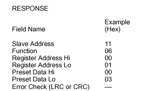
Preset Single Register – Response
Force Multiple Coils (15)
Description :
Forces each coil (0X reference) in a sequence of coils to either ON or OFF. When
broadcast, the function forces the same coil references in all attached slaves.
Query:
The query message specifies the coil references to be forced. Coils are addressed
starting at zero: coil 1 is addressed as 0.
The reguested ON/OFF states are specified by contents of the query data field.
A logical ‘1’ in a bit position of the field requests the corresponding coil to be ON.
A logical ‘0’ requests it to be OFF.
The following page shows an example of a request to force a series of ten coils
starting at coil 20 (addressed as 19, or 13 hex) in slave device 17.
The query data contents are two bytes: CD 01 hex (1100 1101 0000 0001 binary).
The binary bits correspond to the coils in the following way:
Bit: 11 0 0 1 1 01 0 0 000 0 01
Coil: 27 26 25 24 23 22 21 20 – – – – – – 29 28
The first byte transmitted (CD hex) addresses coils 27-20, with the least significant
bit addressing the lowest coil (20) in this set.
The next byte transmitted (01 hex) addresses coils 29-28, with the least significant
bit addressing the lowest coil (28) in this set. Unused bits in the last data byte
should be zero–filled.
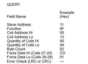
Force Multiple Coils – Query
Response:
The normal response returns the slave address, function code, starting address,
and quantity of coils forced.
Here is an example of a response to the query
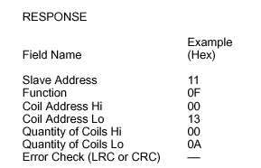
Force Multiple Coils – Response
Preset Multiple Registers (16)
Description :
Presets values into a sequence of holding registers (4X references). When
broadcast, the function presets the same register references in all attached slaves.
Query:
The query message specifies the register references to be preset. Registers are
addressed starting at zero: register 1 is addressed as 0.
The requested preset values are specified in the query data field. M84 and 484
controllers use a 10–bit binary value, with the six high order bits set to zeros.
All other controllers use 16–bit values. Data is packed as two bytes per register.
Here is an example of a request to preset two registers starting at 40002 to 00 0A
and 01 02 hex, in slave device 17:
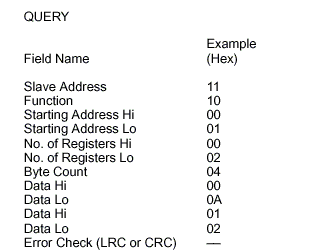
Preset Multiple Registers – Query
Response:
The normal response returns the slave address, function code, starting address,
and quantity of registers preset.
Here is an example of a response to the query
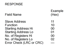
Preset Multiple Registers – Response
Diagnostics (08)
Description :
Modbus function 08 provides a series of tests for checking the communication
system between the master and slave, or for checking various internal error
conditions within the slave. Broadcast is not supported.
The function uses a two–byte subfunction code field in the query to define the
type of test to be performed. The slave echoes both the function code and
subfunction code in a normal response.
Most of the diagnostic queries use a two–byte data field to send diagnostic data or
control information to the slave. Some of the diagnostics cause data to be returned
from the slave in the data field of a normal response.
Diagnostic Effects on the Slave :
In general, issuing a diagnostic function to a slave device does not affect the
running of the user program in the slave. User logic, like discretes and registers,
is not accessed by the diagnostics. Certain functions can optionally reset error
counters in the slave.
A slave device can, however, be forced into ‘Listen Only Mode’ in which it will
monitor the messages on the communications system but not respond to them.
This can affect the outcome of your application program it it depends upon any
further exchange of data with the slave device. Generally, the mode is forced to
remove a malfunctioning slave device from the communications system.
Query:
Here is an example of a request to slave device 17 to Return Query Data. This
uses a subfunction code of zero (00 00 hex in the two–byte field). The data to be
returned is sent in the two–byte data field (A5 37 hex).
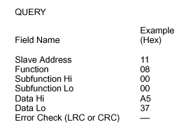
Diagnostics – Query
Response:
The normal response to the Return Query Data request is to loopback the same
data. The function code and subfunction code are also echoed.
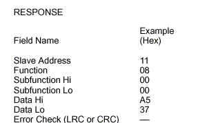
Diagnostics – Response