Communication Models
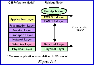
OSI Reference Model : Communication specifications are often explained with reference to the Open System Interconnect
(OSI) layered model. FOUNDATION fieldbus is specified according to the simplified OSI model,
consisting of three (3) layers: Physical Layer (PHL), Data Link Layer (DLL) and Application Layer (APL).
See Figure A-1 for OSI model. Layers 2 to 7 are implemented mostly by software and therefore are
often called the “communication stack.”
Fieldbus Foundation specifies not only
communication but also some user applications, which use FOUNDATION fieldbus communication,
though the OSI model does not specify any user application.Figure A-2 shows the architecture of FOUNDATION
fieldbus.
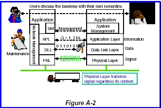
Application Layer of Foundation fieldbus consists of two sublayers: Fieldbus Access sublayer (FAS) and
Fieldbus Message Specification (FMS). FAS is the “glue” to map FMS services to Data Link Layer.
Protocol Data Unit :
Figure A-3 shows how a user data is transferred over the FOUNDATION fieldbus. Each layer appends
layer-control information called Protocol Control Information (PCI) and more information to the
message of the higher layer.
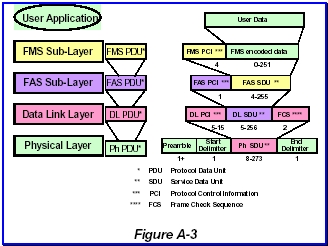
A data unit exchanged between the same layers called “Protocol Data Unit (PDU).” A PDU may
contain an optional data called “Service Data Unit (SDU),” which is a PDU of the next higher layer.
communication layer exchanges other PDUs without SDU to perform its functionality.
Communication through VCR: Messages are exchanged between applications
sitting on the FOUNDATION fieldbus. When a message is transferred, it goes down through a
channel called Virtual Communication Relationship (VCR) to add PCI before it goes to the wire. At the
destination, it goes up through the partner VCR to the receiving application. PCIs are appended and
removed when a message goes through VCRs to allow layers to perform their specific functionality.
See Figure A-4.
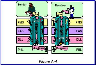
A fieldbus device has many VCRs so that it can communicate with various devices or applications
at the same time. It is possible because the VCR guarantees the message goes to the correct
partner without risks of losing information. A VCR is identified by an application with device-local
identifier called “index” specified in Application Layer. It is also identified from other devices with
DL-address specified in Data Link Layer. A VCR has a queue (fast-in, fast-out memory) or a buffer
(memory to store data) to save messages.
It is the responsibility of network configuration to give the correct information of the index and DLaddress
as well as other operating information to VCRs through Network Management.
Physical Layer
Physical Layer is a mechanism to transmit and receive electric or optic signals to/from medium
that data consisting of ones and zeros is transmitted from one node to the others. Physical
Layer interests are wires, signals, waveform, voltage, and others all related to electricity and optics.
Though the IEC/ISA standard specifies various media with various speeds, Fieldbus Foundation
chose its own subset, low speed wire and fiber media, and Ethernet.
31.25kbps Physical Layer : 31.25kbps Physical Layer is the most common
since IEC and ISA approved it in 1992. In this we deal only wire medium but optical
fiber can be used as an alternative. Though 31.25kbps sounds slow compared with the
latest telecommunication technologies, it is necessary to replace traditional 4-20mA analog
transmissions. It is intended to apply to field devices for various environments of industries.
Many users want to enjoy the simple installation of two-wired transmitters. Explosive gases prevent
high-performance electronics in the hazardous area of the plant. Transmission of 31.25kbps was
chosen for those applications, which demand devices of very low power consumption.
A field device can draw electric current from the medium to feed energy to its electronics. It is
called a “bus-powered” device and is the fieldbusequivalent of two-wire installation.
Signaling Method : Fieldbus utilizes a similar technology for smart
transmitters to transmit an electric signal to the
wire. Figure A-5 shows the electric equivalent circuit of signal transmission. Supply voltage is
applied by a power supply through an impedance conditioner, typically consisting of inductors. DC
current through the impedance conditioner feeds devices. Supply voltage is between 9V and 32V at
the device terminals. The impedance conditioner makes output impedance of the power supply
higher than 400 ohm in the signal frequency bandwidth.
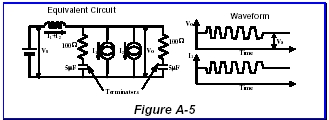
Each cable end is terminated with a terminator of 100 ohm impedance. It makes an instrumentation
cable a balanced transmission line so that a signal of relatively high frequency can be transmitted with
a minimum distortion.
When a device increases its sink current by 10mA, it is fed from capacitors in terminators because the
impedance conditioner of power supply prevents current change through inductors. Thus the
voltage between the wire pair decreases with 0.5V (= 10mA × 50 ohm). In the next moment, the device
increases drawing current by 20mA to generate a modulated signal of 1V p-p amplitude while the
average current remains constant.
Data is encoded as a voltage change in the middle of one bit time. Data one (1) is encoded as a
voltage fall in the middle of the bit time, while zero (0) is encoded as a voltage rise. Additional out-ofband
data are N+ and N- encoded as constant voltage during the bit time. They are used only for
start and stop delimiters to encode the start and end of PHL SDU (= DL PDU) so that Physical
Layer can transmit any combinations of zeros and ones in DL PDU.
Figure A-6 shows the typical waveform of a Physical Layer signal. The receiving Physical
Layer retrieves bit time using the preamble and then the boundary of octets (bytes) using the start
delimiter. The end delimiter indicates the end of the Physical Layer signal. Preamble length can be
increased when the signal goes over repeaters.

Wiring Rules : The IEC/ISA standard specifies minimum amplitude and worst waveform of a received signal
at a device at the any place of the fieldbus network. The Physical Layer receiver circuit must be able to
receive this signal.
You can configure the transmission line in any way as long as the received signal quality is guaranteed
at all receiving nodes. However, it is not always simple and easy. Instead, ISA SP50 committee
created a set of wiring rules to simplify the network design. The received signal is always of better
quality than the minimum requirement if the fieldbus is designed according to these rules. They
sound a little conservative but are useful to design a workable network very easily.
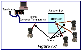
- Number of devices on a fieldbus is between 2 and 32.
- Cable is a twisted pair of individual shield (type A) with 18 AWG wires.
- Overall cable length does not exceed 1900m.
- Overall spur length does not exceed 120m. Maximum number of devices decreases
- according to the spur length as shown in the Table
- When you use multiple twisted pairs with overall shield (type B) with 22 AWG wires, the
total length decreases to 1200m.
| Total Cable Length |
Cable |
| (Type A) 1900m |
Twisted pairs with individual shield |
| (Type B) 1200m |
Twisted pairs with overall shield |
| Devices on the fieldbus |
Total Spur Length |
| (Type A) 1-12 |
120m |
| (Type B) 13-14 |
90m |
| (Type B) 15-18 |
60m |
| (Type B) 19-24 |
30m |
| (Type B) 25-32 |
1m |
I.S Consideration : Intrinsic Safe (I.S.) installation is important for plants where explosive gases exist. I.S. is the rule
to design and install devices in a hazardous area to prevent an explosive gas being ignited by electric
discharge or the surface temperature of a device. An I.S. field device must be carefully designed to
prevent ignition even when a single failure of its component takes place.
An I.S. barrier must be installed to separate the hazardous area from the safe area. A barrier strictly limits the voltage,
current and power fed to a device installed in the hazardous area. Therefore a field device must be
operational with the restricted power supply. Devices and barriers must meet the same design
criteria provided by safety organizations (IEC, FM, CENELEC, PTB, etc.).
Note that I.S. is the only possible technology for zone 0 where explosive gases exist at any time. In
zone 1 where such gases exist most of the time but not always, explosion proof technology is also
applicable as well as I.S. Explosion proof is a technology of housing design and is independent
from fieldbus technologies.
Data Link Layer
Data Link Layer is a mechanism to transfer data from a node to the other nodes that need the data.
It also manages the priority and order of such transfer requests. Data Link Layer interests are
data, address, priority, medium control, and others all related to message transfer. Since Data Link
Layer operates on the low speed Physical Layer, it has mechanisms to use the medium in an effective
way.Foundation fieldbus Data Link Layer is a subset of ISA s50.02 part - 3/4 and type 1 in IEC61158-3/4.
Medium Access Control : The most important functionality of Data Link Layer
is Medium Access Control (MAC) of the fieldbus. Since all devices on the same cable receive the
same Physical Layer signal, only one of them is allowed to transmit signal at a time. MAC is the
method to achieve this goal. The domain of devices sharing the same Physical Layer signal is
called a “link.” In other words, only one device on a link is allowed to use the medium (Physical
Layer) at a time.
Link Active Scheduler (LAS) has the role to control the medium access. Its functionality is explained in
the following sections. The right to send a PDU is called a “token.” The LAS possesses the token
and gives it to another device to allow it to send messages. The token is then returned to the LAS
for further medium access control.
Since application messages have various levels of urgency, Data Link Layer supports a mechanism to
transmit messages according to their urgency. Data Link Layer provides three levels of “priority,”
URGENT, NORMAL and TIME_AVAILABLE, in this order. An URGENT message is transmitted
immediately even when other messages of NORMAL or TIME_AVAILABLE priority are in the
waiting queue, and vice versa. Maximum data size allowed for each priority is shown in Table.
| Priority |
Maximum Data (DLSDU) Size |
| URGENT |
64 bytes |
| NORMAL |
128 bytes |
| TIME_AVAILABLE |
256 bytes |
Addresses :Communication partners in Data Link Layer are identified with DL-address, which consists of three
components, Link, Node and Selector. Link field consists of 16 bits and identifies a
“link.” When the communication is within a link, this field is often omitted. This field is necessary
when a message is going to other links through bridges.

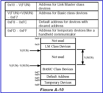
Node field gives the node address of 8 bits. A Foundation device has a node address in the
ranges between 0x10 and 0xFF, which is classified into LM range, BASIC range, default range and
temporary range. Usually devices are in LM or BASIC range according to its device class. When
a device loses the node address, it communicates using one address in the default range. A
temporary device such as a handheld communicator has node address in the temporary
range. Link Active Scheduler has a node address of 0x04.
Figure A-10 shows the address range used in a fieldbus link. There is an address gap of size
V(NUN). If a device has an address in this gap, it will never join the link. V(FUN) and V(NUN) are
parameters you can access through Network management.
Selector field gives a device-internal address of 8 bits to identify a VCR. When a VCR is connected
to another VCR, it is identified with DLCEP (Data Link Connection End Point) shown in this field.
When a VCR is not connected to any others but open to send/receive messages, it is identified with
DLSAP (Data Link Service Access Point) shown in this field. DLCEP and DLSAP have different
ranges. Several DL addresses are reserved for specific purposes. For example, devices can share the
same “global” DLSAP for alarm reception.
Link Active Scheduler: Link Active Scheduler (LAS) has the role to control
the medium access.Foundation devices are classified with device
classes: BASIC, Link Master (LM) and Bridge. A LM class device has a capability to work as the
LAS, while BASIC class devices do not. A Bridge class device has, in addition to LM capability, the
functionality to connect links.
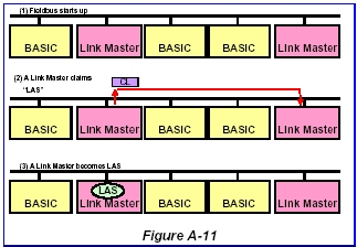
One and only one device in a link works as the LAS. Therefore at least one LM (or Bridge) class
device is needed in a link. LM devices try to acquire LAS role when no LAS exists on start up or
when the current LAS fails. The LM device with the least node address wins this contention. Other LM
devices observe the LAS activity and take over its role when LAS goes away. Figure A-11 shows the
procedure through which a Link Master class device becomes the LAS.
Note that the LAS is an additional functionality to basic communication. Therefore it has a different
DL-address (0x04) than the node address.
Scheduled Communication:
The LAS is responsible for scheduled communication, which is necessary to link Function
Blocks. Function Blocks are distributed applications operating in a synchronized manner.
The LAS manages the communication part of the synchronized data transfer.
A Function Block output parameter is a “Publisher” of data and other Function Blocks that receive this
data are called “Subscribers.” The LAS controls periodic data transfer from a Publisher to
Subscribers using the Network Schedule.
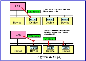
When the time of scheduled communication comes, LAS sends Compel Data (CD) PDU to the
Publisher DLCEP. Publisher is expected to transmit Data Transfer (DT) PDU stored in the data
buffer of the DLCEP immediately. When Subscribers receive CD to the Publisher, they
presume the next data transfer comes from the Publisher. Received data is stored in the buffer of
Subscribers. A CD PDU is a token for a Publisher and the LAS interprets the publishing DT PDU as
the returned token.Data Link Layer appends “freshness” information as PCI to the data so that the Subscribers know
whether data has been updated since the last publish.
Unscheduled Communication: Other communications take place in an
asynchronous way. The LAS is responsible to give all nodes on a link a chance to send messages.
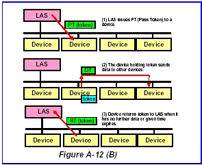
The LAS gives a token by sending Pass Token (PT) PDU to a node. A PT PDU contains priority
and time interval information. When the node does not have messages of the given or higher priority to
be sent, or the given time interval is expired, it returns token as Return Token (RT) PDU.
The LAS controls the message transfer by updating the priority. When the token is given to all
devices in a short time interval, the LAS gives more time to the nodes by lowering the priority. When
the token does not go to all devices within a “target token rotation time” network parameter, the LAS
increases the priority so that the token is given to all devices in a desired time interval.
A device must return the token within the time interval given in the PT PDU. This is necessary to
finish the unscheduled communication before the next scheduled communication.
Note that the token is given to the node instead of DLCEP or DLSAP. Therefore the device is
responsible to allow all DLCEPs and DLSAPs in the device to send messages.
Link Maintenance: The third role of LAS is to maintain the link. The
LAS gives the token to all devices detected by the LAS. When a new device is added to the network,
it must be recognized by the LAS and entered to the token rotation list called “Live List”.
The LAS sends a Probe Node (PN) PDU to node addresses where a device was not found before. A
new device waits until it receives PN and returns Probe Response (PR) PDU to the LAS. Then the
LAS adds this device to the Live List after activating the full DLL functionality of the device.
This probing is repeated in a given
interval.
When a device is removed from the link, it does not respond to PT any more. The LAS detects this and
deletes the device from the Live List. Whenever a change is detected in the Live List, the
LAS broadcasts the change so that all LM devices share the latest list and are ready to take over.
The LAS also broadcasts its Data Link Time (LStime) to the link in a predefined interval so that all
devices on the network share the same time, which is necessary to start Function Blocks. It is often
called “network time.”
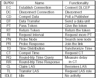
Data Link PDUs: Table summarizes Data Link Protocol Data Units (DL PDUs) in FOUNDATION fieldbus.
Application Layer
The Application Layer consists of two sublayers.
Fieldbus Access Sublayer (FAS) manages data transfer while Fieldbus Message Specification
(FMS) encodes and decodes user data.
Fieldbus Access Sublayer:
Fieldbus Access Sublayer (FAS) is a part of secure communication. Since fieldbus does not have
layers (4 to 6) between DLL and APL, FAS directly maps APL requests to DLL services. This is the
most important part of VCR management. The FAS provides three communication models for
applications. They are explained below and summarized in Table. It is expected a network
manager configures VCRs correctly according to the models communicating with each other. Once
configured, FAS provides the communication facility according to these models.
| Model |
DLL |
Schedule by |
Direction |
| Client-Server |
Queued |
User |
Bi-direction |
| Publisher-Subscriber |
Buffered |
Network |
Uni-direction |
| Source-Sink |
Queued |
User |
Uni-direction |
Client-Server Model: The Client-Server model is universal and used in
many communication technologies. An application called “Client” requests another application called
“Server” to do a specific action through FMS. When the Server finishes the requested action, its
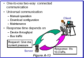
result is transferred to the Client. It is a one-to-one two-way communication using DLCEP.
A typical example is a human-machine interface (Client) to read data of a Function Block (Server).
The Client sends a Read request to the Server and then Server sends back the data to the Client. This
communication takes place at any moment. A Client may want to issue many requests at a
time. Client-Server VCR has a queue to store those requests and sends requests one by one
when the node has a token. A flow-control mechanism is available to manage error recovery
and Server’s processing power.
Publisher-Subscriber Model: Publisher-Subscriber model is designed to link
Function Blocks. When a publishing Function Block runs, its output data is stored in the buffer of
the Publisher VCR. Then the LAS sends CD to the VCR to force it to transfer the data in DT PDU.
Subscriber VCRs receive this PDU and gives the data to the subscribing Function Blocks.
A typical example is a linkage from output of an Analog Input (AI) block to process value input of
PID control block.
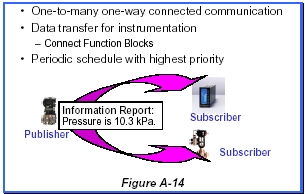
The Publisher-Subscriber model is one-to-many one-way communication using DLCEP.
Subscribers are able to know whether data has been updated since the last publish. This
mechanism is important because Data Link Layer transfers data as scheduled regardless if the
publishing Function Block updates the data in the buffer.
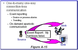
Source-Sink Model: The Source-Sink model is designed to broadcast
messages. It is one-to-many one-way communication without schedule. This model is
sometimes called “Report Distribution Model.” A Source VCR transfers a message in the queue to
an assigned global DLSAP address when the device has the token. Sink VCRs have the same
global address and receive the same message from a Source.
Foundation devices use this model for two specific purposes. One is to report alarms or events
detected in the Source, and the other is to transmit trend of Source Function Block. Alarms are
acknowledged through a Client-Server VCR. It is desirable for an alarm logger to receive alarms
from devices with one VCR. A Sink can receive messages from many Sources if the Sources are
configured to send messages to the same global address. A Sink can identify the Source with its
DLSAP address.
Fieldbus Message Specification:
Fieldbus Message Specification (FMS) is a service interface for user applications to use fieldbus
services. When a service is requested, it encodes the request to transfer it to the other applications.
The receiving FMS decodes the request to notify the application.
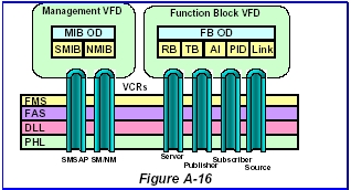
Virtual Field Device (VFD):
A fieldbus device may have user applications, which are independent from each other and do not
interact. A fieldbus device consists of Virtual Field Devices for such individual applications. An
identifier, given to a VCR, identifies the VFD. A Foundation device has at least two VFDs. One
is Management VFD where network and system management applications reside. It is used to
configure network parameters including VCRs as well as to manage devices in a fieldbus system.
The other is a Function Block VFD where Function Blocks exist. It is possible for a field device to have
two or more Function Block VFDs.
FMS Objects: Applications in a VFD are shown to other applications on the network using an “object
model,” which consists of attributes, its behavior and access methods.
Object Examples: Function Blocks have parameter objects to which
another application can have access. Alarms, Function Block Linkage are also objects. Their
behavior is specified in the Function Block Application specification. Network behavior is managed through Network
Management Information Base (NMIB) objects. System behavior is managed through System Management Information Base (SMIB)
objects. Schedules and VCRs are also objects.
Object Dictionary: An object is identified with a number called “index,”
which is unique within the VFD. Additional information to describe an object is necessary for
open systems. Such information is called the “Object Dictionary (OD),” which is an assembly of
information called “Object Descriptions” to explain the objects.
A Client application can read such explanations with “Get OD” service and read the value when the
object is a variable.
The most fundamental object is a “variable” to contain a value. It may be a simple variable, a
record (structure) or an array. Function Block parameters, VCR, NMIB and SMIB are examples
of record variables.
Other objects are event, domain, and program. They are explained in the next sections.
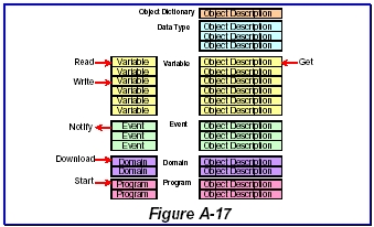
An object is accompanied with its Object Description sharing the same index. There are
Object Descriptions without associated objects. Those Object Descriptions give other information
such as object location, amount of objects, data type, data structure and so on.
FMS Services: FMS provides services to access FMS objects. Tables summarize them with service classes.
Variable Access:
A variable is storage of data. Its value can be read or written by another application. An application
can send variable data without request from another application using Information Report
service. Foundation fieldbus uses this service in publishing data and reporting trends. It is possible
to define a list of variables for an effective transfer. When a variable is a record or an array and
consists of multiple variables, it is possible to transfer it as a whole or only one component
assigned with “sub index.”
| Read |
Read value of a variable |
| Write |
Write value to a variable |
| Define Variable List |
Define a list of variables to send |
| Delete Variable |
Delete a list of variables |
Table - Variable Access Services
Event Management:
Event is used to notify that an application detects something important. Failure, data update and
alarms are examples of events. An event is notified with the Source-Sink model repeatedly until
it is acknowledged through the Client-Server model. Its notification can be enabled or disabled
through another Event-related service.
| Event Notification |
Report an event as Source |
| Acknowledge Event Notification |
Acknowledge an event |
| Alter Event Condition
Monitoring |
Disable or enable an event |
System Management needs additional protocols to manage fieldbus systems. It must be operational
even under abnormal situations such as system startup, wrong configuration, device failure and its
replacement. Its protocol is called “System Management Kernel Protocol (SMKP)” and it
directly uses Data Link Layer services without the Application Layer.
Though the Fieldbus specification allows faster media such as 1Mbps and 2.5Mbps, very few
people are interested in using them. 31.25kbps Physical Layer has its niche to replace 4-20mA
transmissions in plant floor and work in a hazardous area. Other Physical Layers are giving
their places to the state-of-art technologies.

